VeriColor Spectro alarm output testing
Stack light or other alarm connected to VeriColor Spectro is not functioning properly.Verify wire connections and manually test outputs.Using Discrete Interface Cable (PN SE108-EUR-5M)
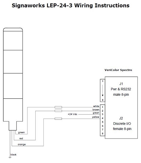
#1 – Pass(white)
#2 – FAIL(brown)
#3 – Output Comm(green)
#4 – CH-E 16 / ‘Action’(yellow)
Connecting a stack light or other 24VDC 2A max alarm.
Using ToolCrib or other serial port connection software connect to the serial port the VeriColor Spectro is on.
To check stack light:
- To manually send commands to turn on different lights.
- Type "0100io" (zero, one, zero, zero, letter I and letter o) in the command line of Tool Crib then click Send. Close contact for green light. (Close contact Pin 3 to Pin 1 on VS410 Discrete I/O cable)
- Type "0200io" (zero, two, zero, zero, letter I and letter o) in the command line of Tool Crib then click Send. Close contact for yellow light. (Close contact Pin 3 to Pin 4 on VS410 Discrete I/O cable)
- Type "0400io" (zero, four, zero, zero, letter I and letter o) in the command line of Tool Crib then click Send. Close contact for red light. (Close contact Pin 3 to Pin 2 on VS410 Discrete I/O cable)
- Type "0000io" (zero, zero, zero, zero, letter I and letter o) in the command line of Tool Crib then click Send. Open contact for no light.